| [ Team LiB ] |
|
Modeling TechniqueUMLThe Unified Modeling Language (UML) has evolved into an industry standard for documenting the components of an object-oriented system. The construction of a model that maps to the real-world object is half the solution to the problem. The model abstracts the necessary details of the software problem and maps the real-world objects to their corresponding software system artifacts. This section gives a short introduction of UML. Because UML is a language itself, it provides its own set of rules, notations, and syntax. The notations are used in a set of specialized software diagrams that represent different facets of the solution. The notations are governed by a set of rules and the diagrams are created by combining the shapes to conform to the UML syntax. UML is managed by the Object Management Group (OMG) and was greatly influenced by other object-oriented analysis and design techniques. Most of the notations have been adopted from two of the most popular techniques: Rumbaugh's object modeling technique (OMT) and Booch's object-oriented design (OOD). For a full specification of UML, refer to the OMG's site at http://www.omg.org/uml. Now let's take a brief look at the different notations available as part of UML. UML DiagramsOverviewEach of the UML diagrams is designed to give a different perspective to the different parties involved in a software solution. The degree of abstraction also varies from diagram to diagram. UML defines the diagrams representing the different perspective of the problem as grouped in the following major categories. There is no hard-and-fast rule on the category because these diagrams can be subcategorized even further. Table 5.3 summarizes the UML diagrams.
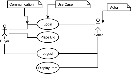
Apart from those listed in Table 5.3, there are model management diagrams that include packages, subsystems, and models. Creating these diagrams appears to be a lot of work, but UML has evolved into a popular standard and the number of tools that help create these diagrams has increased. Now let's see some of the diagrams in detail with the help of the global auctions management system described earlier in the chapter. Use Case DiagramThis diagram describes what a system does. A use case is a summary of all the scenarios for completing a task. Let's take the case of the global auctions system in which a one-time user (guest) is one of the actors. Figure 5.7 illustrates all the communications between the guest and the related use cases. Figure 5.7. Use case diagram.
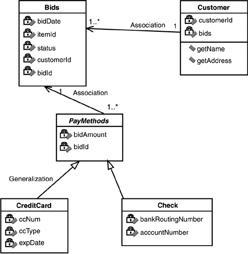
As you can see, these diagrams are an effective way of representing the functionality and communicating the business process to clients. Class DiagramAs Figure 5.8 illustrates, class diagrams are an effective way of representing a system overview with its classes and the relationships among them. Figure 5.8. Class diagram.
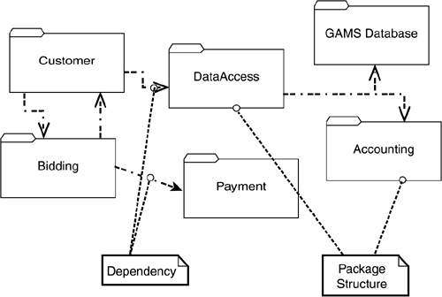
Package DiagramPackages organize the classes into well-defined groups. Figure 5.9 illustrates part of the sample package structure for the global auctions application. Figure 5.9. Package diagram.
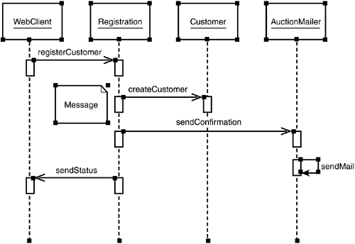
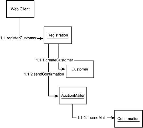
Sequence DiagramA sequence diagram is an interaction map that represents how operations are executed over time. Figure 5.10 illustrates part of the sample sequence diagram for the customer registration process. Figure 5.10. Sequence diagram.
Collaboration DiagramThe collaboration diagram is an interaction chart similar to the sequence diagram, but the focus is on the object roles instead of the times that messages are sent. Figure 5.11 illustrates part of the sample collaboration diagram for the customer registration process. Figure 5.11. Collaboration diagram.
Activity DiagramThe activity diagram is a sophisticated flowchart and it shows how the different activities are interdependent. Figure 5.12 illustrates part of the sample activity diagram for the auction closing process. Figure 5.12. Activity diagram.
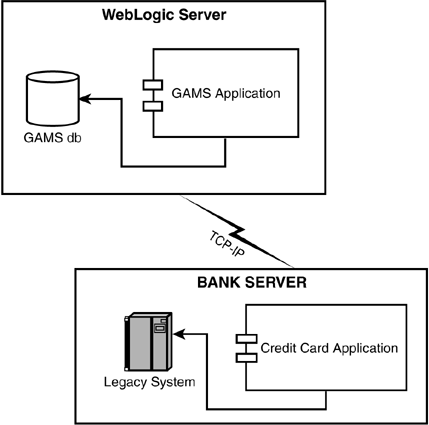
Deployment DiagramA deployment diagram represents the physical configurations of the system. Figure 5.13 illustrates the deployment diagram for part of the global auctions system. Figure 5.13. Deployment diagram.
We just saw some of the different UML diagrams that give different users their perspective of the system. Now let's move on to the MVC pattern, which gives an effective design strategy for the enterprise applications we discussed earlier. |
| [ Team LiB ] |
|